What is BLDC?
1. BLDC is called Brushless DC Motor (Brushless DC Motor), divided into three-phase and single-phase, mainly three-phase.
2. The working method of BLDC is to use electronic commutation, which does not require carbon brush commutation.
3. (1) Advantages: long life, low noise, high efficiency, flexible control;
(2) Disadvantages: high cost and complicated control.
4. BLDC control method: square wave control, sine wave control, FOC control
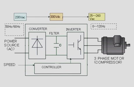
5. DC voltage control
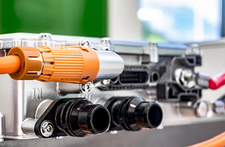
6. Application
7. Power
8. Motor structure: inner rotor, outer rotor, star, delta
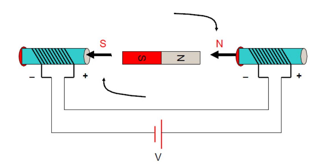
Electromagnetic principle
1. Rule of left and right
F = BIL*sinθ
B is the magnetic induction intensity (unit T), I is the magnitude of the current (unit A), the effective length of the conductor (unit L m), F is the magnitude of the force
2. Electromagnetism
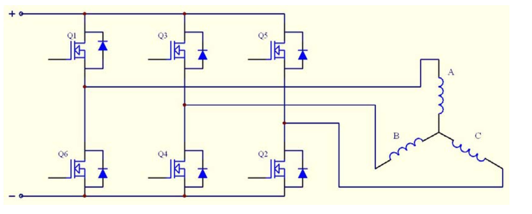
 BLDC switching circuit
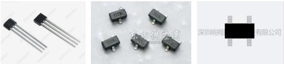
 Introduction to Hall Sensor
A Hall sensor is a type of magnetic sensor. It can detect the magnetic field and its changes, and can be used in various occasions related to the magnetic field. This phenomenon was discovered by Hall (A.H.Hall, 1855-1938) in 1879 when he was studying the conductive mechanism of metals. Later, it was found that semiconductors and conductive fluids also have this effect, and the Hall effect of semiconductors is much stronger than that of metals. Various Hall elements are made using this phenomenon.
The Hall voltage changes with the strength of the magnetic field. The stronger the magnetic field, the higher the voltage, the weaker the magnetic field, and the lower the voltage. The Hall voltage is very small, usually only a few millivolts, but it is amplified by the amplifier in the integrated circuit. This voltage can be amplified enough to output a stronger signal
The relationship between electrical angle and mechanical angle
1. 120-degree electrical angle commutation principle: According to the six-step commutation conduction sequence, we can obtain the conduction sequence of each switch. If the voltage conduction time of each phase is compared to the conduction angle, then the conduction angle of each phase is 120 degrees.
2.12-slot 10-pole motor (example of 4038 motor)
180*10/12 = 150 (electrical angle between each slot)
1 5 9 slots can be calculated as the mechanical angle of Hall placement
1 slot is 0 degrees (U) 5 slots is 600 degrees, which is 240 degrees (W) 9 slots is 1200 degrees, which is 120 degrees (V)
 Six-step commutation principle (current waveform)
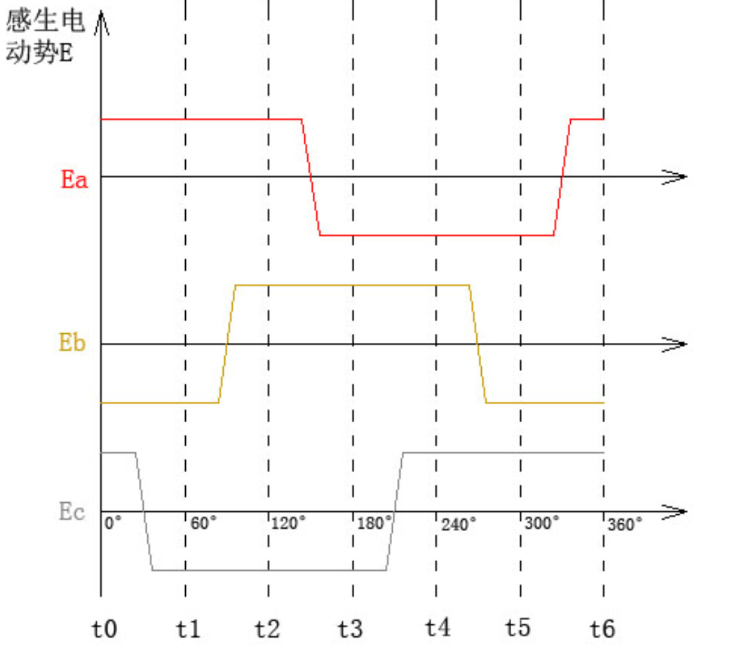
 Six-step commutation principle (back EMF waveform)
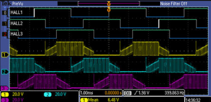
 Six-step commutation principle (phase line waveform)
 Six-step commutation principle (phase line waveform)
 The principle of FOC vector control technology
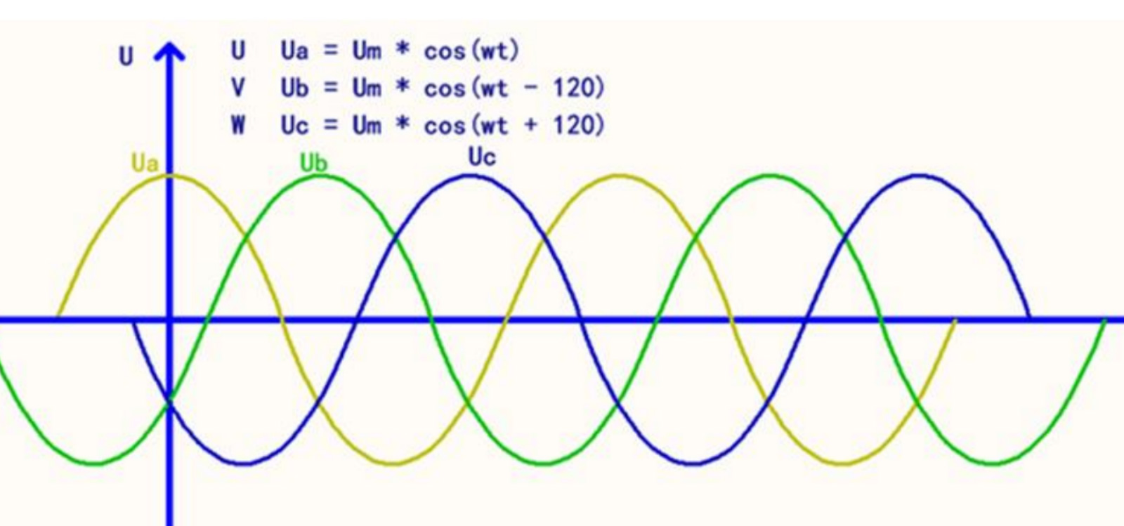
1. FOC actually refers to field-oriented control, which controls both the direction of the current and the direction of the voltage. The following figure is its three-phase symmetrical sinusoidal AC waveform diagram
 The principle of FOC vector control technology
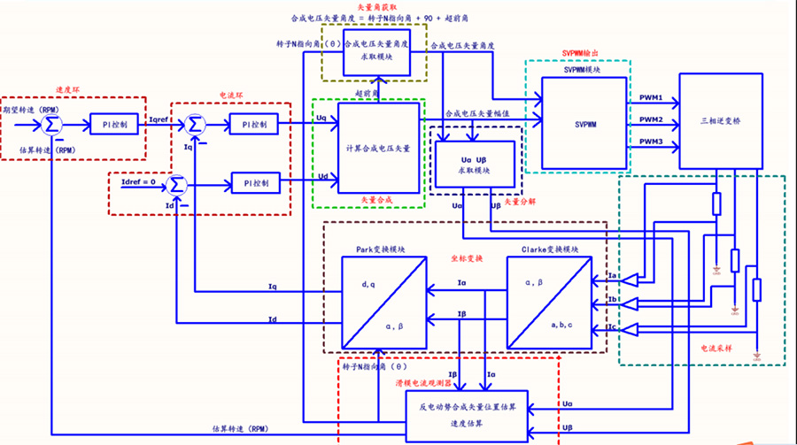
2. The overall control block diagram of FOC, as shown below
 The principle of FOC vector control technology
(1) Motor drive control technology such as FOC is actually an extremely complex set of theoretical systems. It was first proposed by German engineers in the 1970s, and it can be converted into various waveform signals by simply controlling the current to finally control the operation of the motor.
(2) The control flow of the software algorithm, current acquisition-clarke transformation-park transformation-reverse park-svpwm-output three mutually symmetrical 120-degree sinusoidal waveforms
(3) Angle algorithm production includes Kalman filter and synovial film SMO filter, which are mainly used to produce information such as the actual angle of the motor, feedback speed and other feedback control quantities.
(4) FOC's software control algorithm actually has relatively high performance requirements for the MCU, with a main frequency of at least 48M and a flash capacity of at least 32K.
The use of FOC algorithm on high-speed fans
The main frequency of the chip is 64MHZ, dual-resistor sampling, FOC vector control algorithm, and the motor speed can reach up to 110000RPM.
Development prospects and technological innovation
1. BLDC has been widely used in various fields due to its high efficiency, long life and many other advantages, especially in home appliances, such as fans, water pumps, physiotherapy equipment and other occasions where motors are replaced on a large scale.
2. The volume can be made small, the control is simple, and the digital operation can be realized
3. The rotor technology with rare earth materials as the core still needs a relatively large room for innovation
shénme shì BLDC?
1.BLDC quánchēng wèi zhíliú wú shuā diànjī (Brushless DC Motor), fēn wèi sān xiàng yǐjí dān xiàng, zhǔyào yǐ sān xiàng wéi zhǔ.